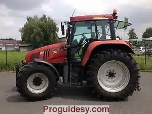
Case Steyr CS 110 120 130 150 CS110 Workshop service manual
This is the COMPLETE workshop manual for tractors from the CASE CS series (models 110 120 130 150).
You can use this manual for Steyr tractor models:
9105a, 9115a, 9125a, 9145a
The files have over 1780 pages! (fully digital version)
Language: English
Main sections:
2 ENGINE
Disassembly and assembly
Workshop manual (from DBD0075001)
3 FUEL SYSTEM
How it works – injection system (from DBD0075001)
Removing and installing injection pump (up to DBD0015192)
4 ELECTRICAL
How It Works and Troubleshooting – Combi Instrument
Electrical diagram (GE / EN)
Electrical diagram (post-power shuttle)
circuit diagram
5 STEERING SYSTEM
How it works, troubleshooting and settings
Front axle with 20.25S independent suspension
Workshop manual – front axles 20.20 and 20.25 (GE / EN)
Independent suspension front axle 20.25S
6 GEARBOX
How it works – T 7200 gearbox
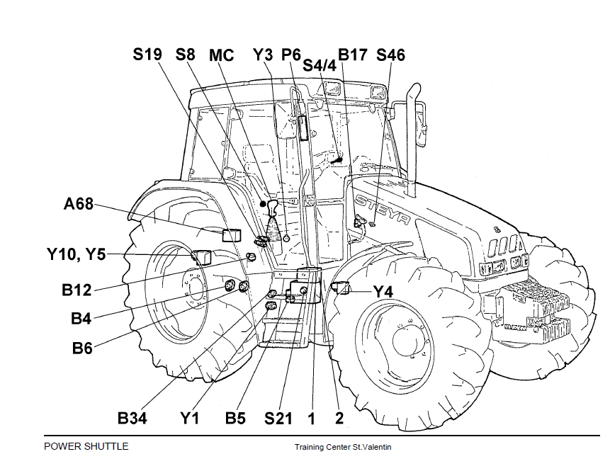
How It Works – Power Shuttle (Supplement to Section 6)
How it works and troubleshooting-
Transmission control electrical and electronic (up to power shuttle)
How it works and troubleshooting electronic box forward / backward (up to power shuttle)
How it works – ECCU (Electronic Central Control Unit)
How it works and troubleshooting – PTO control and PTO management
Troubleshooting the transmission control – electrical and electronic (post-power shuttle)
Troubleshoot all-wheel and differential locks (versions after Power Shuttle)
Disassembly and assembly of gearbox T 7200
Disassembly and assembly of the power shuttle coupling (supplement to chapter 6006)
8 HYDRAULIC SYSTEM
How it works – OC / LS hydraulic system (Open Center-Load Sensing)
How it works and troubleshooting-OC hydraulic system (Open Center)
How it works and troubleshooting-Electronic Hitch Control EHR-D
How it works – CC / LS hydraulic system (closed center load sensing)
Circuit diagram CC / LS hydraulics with sprung front axle
Wiring diagram CC / LS hydraulics with sprung front axle and hydr. trailer brake
Circuit diagram CC / LS hydraulics with all-wheel brake
Circuit diagram CC / LS hydraulics with hydr. Trailer brake and all-wheel brake
Troubleshooting the high pressure hydraulic circuit
with load-sensing control units
Hydraulic circuit diagram up to the power shuttle version
Hydraulic circuit diagram from the power shuttle version with sprung front axle
Load sensing – hydraulic valves for constant pumps
Load-sensing (LS) block assembly drawing
Troubleshooting the low pressure hydraulic circuit (P1-18bar)
Troubleshooting the high pressure hydraulic circuit
Versions after the PFC reciprocating pump


