John Deere 3215A, 3215B, 3225B, 3235A and 3235B Mower Technical Manual
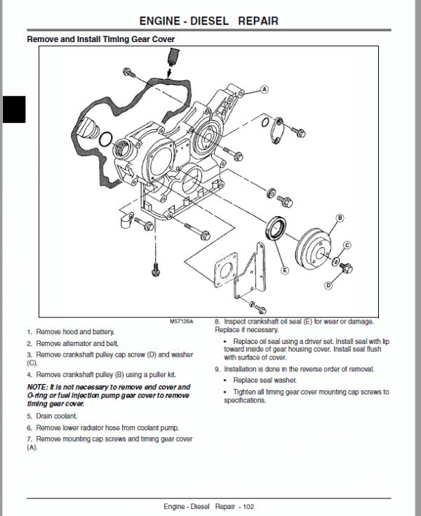
This manual includes illustrations like pictures and diagrams which you can help you determine the installation location spare parts, etc.
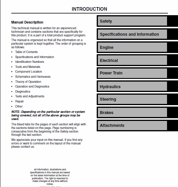
Safety
Specifications and Information
Engine – 3TNE75-RJF
Engine – 3TNE78-JFM
Electrical
Gear Power Train
Steering and Brakes
Hydraulics
Miscellaneous
The listing is for :
John Deere 3215 manual,
John Deere 3215A manual,
John Deere 3215B manual,
John Deere 3225B manual,
John Deere 3235 manual,
John Deere 3235A manual and
John Deere 3235B manual
These are concise service guides for a specific machine and are on-the-job guides containing only the vital information needed by a technician and includes repair and maintenance information, detailed description of service and troubleshoot procedures, installation instructions, special instructions, other additional information.
This manual includes illustrations like pictures and diagrams which you can help you determine the installation location spare parts, etc.
John Deere 3215A, 3215B, 3225B, 3235A and 3235B Mower Technical Manual
Diagnostics of the Steering Wheel
Steering System Troubleshooting
Symptom: Steering Wanders
(1) Are tires of proper type and inflated to proper pressure
Yes – Go to step (2).
No – Replace tire with tires of proper type. Inflate tire(s) to proper pressure.
(2) Is hydraulic system free of air Hydraulic fluid not aerated
Yes – Go to step (3).
No – Purge air from system. Check suction line to charge pump for air leaks.
(3) Are the hydraulic fittings tight, preventing fluid loss
Yes – Go to step (4).
No – Tighten hydraulic fittings.
(4) Are the steering cylinder ball joints in good condition, not worn
Yes – Go to step (5).
No – Replace parts as needed.
(5) Is the steering linkage in good condition, not damaged or worn
Yes – Go to step (6).
No – Repair or replace parts as necessary.
(6) Perform steering system leakage test. See Test Steering System Leakage on page 370. Is test within specifications
No – Perform steering valve leakage test. See Test Steering Control Unit (SCU) Leakage on page 370.
Follow results of test.
Install Rear Wheel Motor – Four-Wheel Drive Only
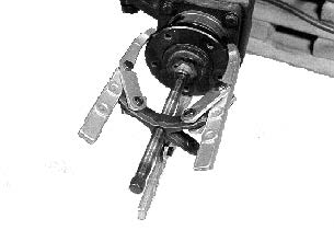
1. Place hydrostatic motor in rear axle housing.
2. Position motor so the fittings on the backplate of the motor face rear of the machine.
3. Install four bolts through motor mounting flange and into rear axle housing. Tighten to specifications.
4. Install hydraulic lines on motor.
5. Place disk on motor shaft and install nut. Use pipe wrench to keep disk from turning if not using air tools.
Tighten to specifications.
6. Install wheel and tire assembly.
7. Start machine and operate motor to determine if motor rotates in the proper direction.
If motor rotates in wrong direction, the hydraulic lines are reversed or timing procedure of the motor is incorrect. See Motor Assembly for proper timing procedure.
Specifications
Rear Axle Housing Bolt Torque (4 used) . 140 Nm (105
lb-ft)
Disc Torque. . . . . . . . . . . . . . . . . . . . . 190 Nm (140 lb-ft)




Reviews
There are no reviews yet.