Komatsu CK20-1 Service Repair Manual
Komatsu CK20-1 Skid-Steer Loader Service Manual
Komatsu Skid-Steer CK20-1
Publication: WEBM006400
Format: PDF
Language: English
The Komatsu CK20-1 Skid-Steer Loader Service Manual is of 298 Pages
Table of Content of the Komatsu CK20-1 Skid-Steer Loader Manual:
10. STRUCTURE AND FUNCTION… 10-1
20. TESTING AND ADJUSTING … 20-1
30. REMOVAL AND INSTALLATION…30-1
40. MAINTENANCE STANDARD… 40-1
90. OTHER…90-1
This CK20-1 shop manual is an aid to improve the quality of repairs by giving the operator an accurate
understanding of the product and by showing him the correct way to perform repairs and make judgements. Make sure
you understand the contents of this manual and use it to full effect at every opportunity.
This shop manual mainly contains the necessary technical information for operations performed in a service
workshop.
The manual is divided into chapters on each main group of components; these chapters are further divided into the
following sections.
Komatsu CK20-1 Service Manual
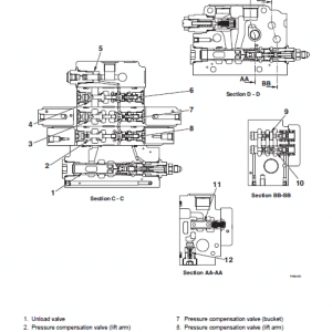
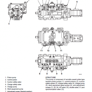
STRUCTURE AND FUNCTION
This section explains the structure and function of each component. It serves not only to give an understanding
of the structure, but also serves as reference material for troubleshooting.
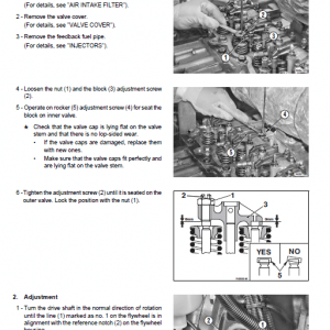
TESTING AND ADJUSTMENTS
This sections explains checks to be made before and after performing repairs, as well as adjustments to be made at completion of the checks and repairs.
Troubleshooting charts correlating Problems to Causes are also included in this section.
REMOVAL AND INSTALLATION OF THE CK20-1 SKID-STEER
This section explains the order to follow when removing, installing, disassembling or assembling each component, as well as precautions to be taken for these operations.
STANDARD MAINTENANCE
This section gives the judgement standards when inspecting disassembled parts
ADJUSTMENT OF THE PPC VALVE CLEARANCES
The clearance of the PPC valve (hand and foot) levers is adjust as follows.
k Lower the working equipment to the ground and stop the engine.
Turn the ignition key to the I position and move the control levers in all directions in order to release all pressure in the hydraulic circuits.
Return the ignition key to the O (OFF) position and remove it.
Slowly loosen the oil-tank fill cap to eliminate residual pressure.
1 – Remove boot (1).
2 – Loosen the nut (2) that retains the disc (3).
3 – Tighten the disc (3) until it makes light contact with the 4 push-rods (4).
a During this adjustment, take care not to activate any of the push-rods (4) individually.
4 – Secure this position by tightening the retaining nut (2) to the specific torque. 3Retaining nut: 11315 Nm






Reviews
There are no reviews yet.